Step 1 — Check the Transmitter Display
Does the transmitter have a display, and is it showing something?
Step 2 — Check the Terminals
Can you safely remove the cover and check the terminals? Only do this if you are trained, authorized, and it’s safe to do so.
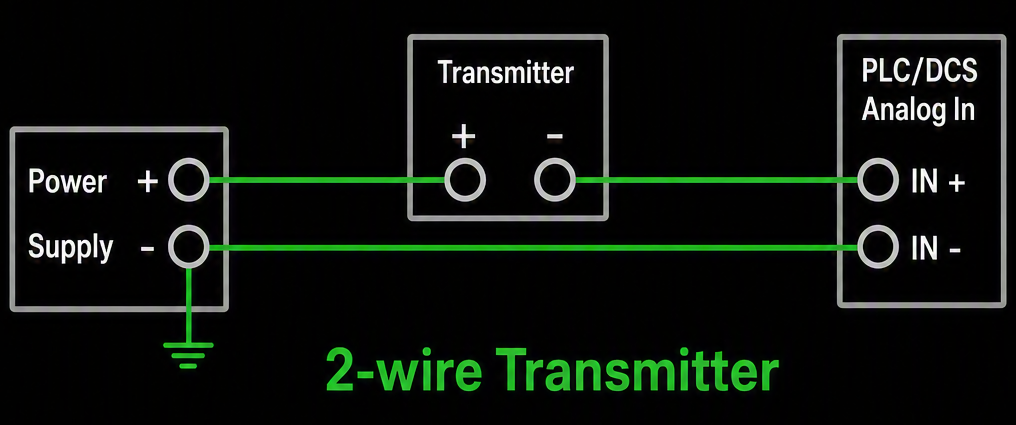
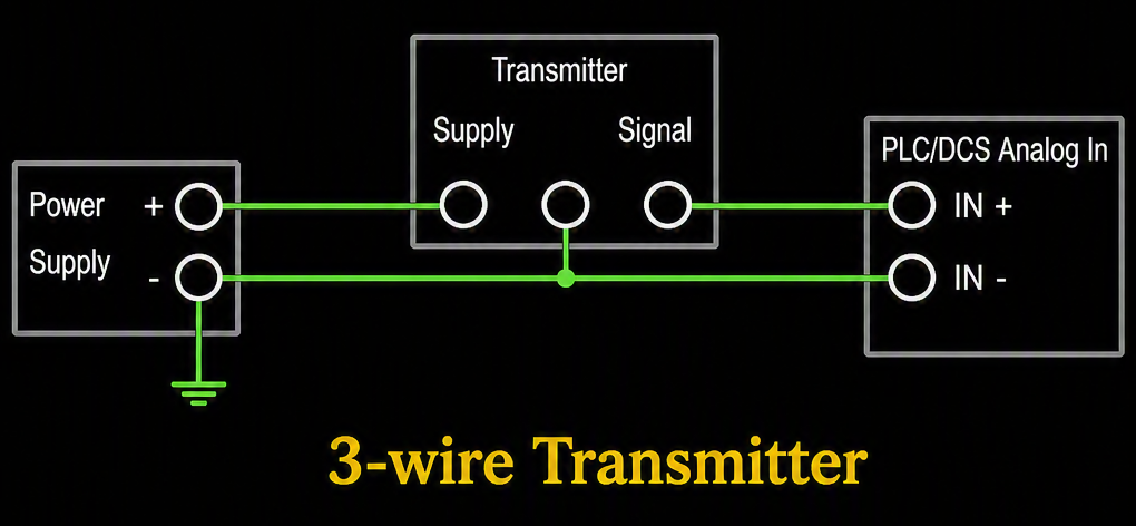
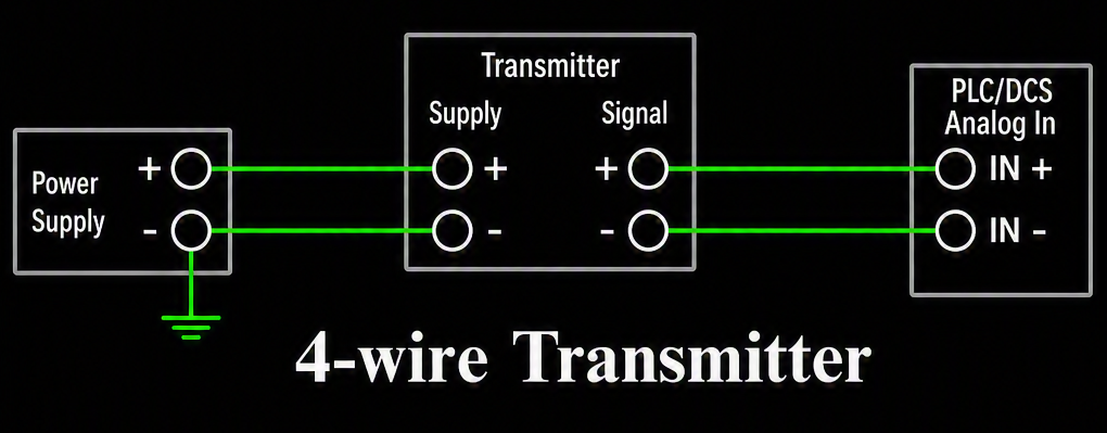
Step 3 — Check Voltage
With the loop still powered, set your multimeter to DC Volts and measure directly across the two power terminals (meter leads in parallel with the terminals — no need to disconnect anything). Expect roughly 24V minus the wiring/device drop, or the value on your loop drawing.
If you read no voltage: check the power supply output, check the fuse or breaker feeding the loop, and check the terminals for a loose or corroded connection. A missing wire is the most common cause.
If voltage looks correct: the transmitter is getting power — move on to checking current below.
Step 4 — Check Current
Set your multimeter to DC mA. If your terminal block has a built-in test/disconnect jack, use that to insert the meter in series — that’s what it’s there for. Otherwise use a clamp-on mA meter so you don’t have to break the loop. Expect a steady reading between 4 and 20 mA.
If voltage is present but current is 0 or stuck: the transmitter itself may be faulted, there may be an open wire further down the loop, or the transmitter could be stuck in a fixed test/simulation mode — check its local configuration.
A fuller guided walkthrough for loops without test terminals is coming soon.